

Five Reasons to Reconsider Fiber
New standards ensure that fiber optic cables will bring big opportunities to machine vision
Fiber optic cables and networks typically get headlines because of the data speeds the technology enables. Copper has come a long way in the last twenty years, but is approaching its speed and distance limits due to the laws of physics. Different physics laws apply to fiber technology and as a result researchers are pushing 50 and 100 Gbps rates in the labs while 25 Gbps rates are being deployed today in data centers. Trans-oceanic cables can support multiple channels within in one fiber using wavelength division multiplexing, and a cable about the thickness of a garden hose can support terabits per second of bandwidth.
While the machine vision industry has been slow to adopt fiber cabling, this is changing with the availability of very low cost 10 Gbps transceivers and low cost LC patch cables. One of the drivers to adopt fiber is the need to transfer the data now easily available from high speed CMOS sensors and the need for improved vision inspections at ever-faster rates.
Setting a Higher Standard
The Japan Industrial Imaging Association (JIIA) has embarked on an initiative to define an optical connector for use in machine vision. The JIIA has identified 4 basic types of optical interconnect. These types of interconnect differ depending on where the optical engine is located in the system. The optical engine does the conversion from electrical to optical signals. Type I places the optical engine deep inside the unit and runs a small fiber to the unit’s fiber connector on the case. Type II moves the optical engine into a module located at the case and this unit includes the optical connector the customer would plug into. Type III presents an electrical interface which the customer plugs into an optical engine like an SFP+ module, or an Active Optical Cable where the cable includes the optical engine inside the connector housing. USB3 optical cables are commonly made this way. The other JIIA types include power with optical fiber but have a limited number of fiber lanes.
Although the speed advantages are significant, the hesitation of the industry to adopt fiber optic cabling has been for other reasons, both real and imagined. But fiber has come a long way, and with more robust cabling, falling material prices, and other advancements in related technologies, it looks like fiber’s time may finally have arrived.
But what else can it do? Today it turns out that fiber optic cabling can compete with traditional copper cabling for a few reasons.
Reason #1: Long Distance
Fiber has very low attenuation loss over long distances compared to copper cabling. The typical attenuation for multimode fiber over a 100-meter distance is 0.3 dB, meaning it loses only 3% of its original signal strength. Also, the attenuation of fiber doesn’t change as bit rates increase. By comparison, typical Category 6a cable over 100 meters at 500 MHz is about 20 dB which is a 90% loss in signal strength.
Reason #2: Immunity to Electromagnetic Interference
Optical fiber is immune to electromagnetic energy because it doesn’t conduct electric current. Copper cables essentially act as an antenna to pick up electromagnetic signals from other electrical systems that are common in an industrial environment. Copper cabling, if not installed properly, is vulnerable to interference which can cause errors, degradation, or complete system failure. Copper wires need to be carefully shielded in high-demand confined environments, such as in airplanes and military applications. In contrast, optical cables can be strung on poles alongside high voltage power cables and are even immune to the electromagnetic pulses generated by nuclear devices.
Reason #3: Durability
Copper cable is delicate, with only a 25-40 pound tension limit. Basic fiber has a 100-200 pound tension limit and there are many varieties (for resisting everything from water and fire to rodents and crushing loads). It is also much stronger, with eight times the pulling tension of copper wire and is often made with strength members and stiffeners that make it much harder to damage or kink. These are usually made from aramid yarn, the same used in bulletproof vests, which absorbs the tension needed to pull the cable and provides cushioning for the fibers. While telecom cabling is not typically flex-life rated, machine vision specific cable solutions even accommodate robotic systems, where the camera itself is constantly in motion. Fiber cabling doesn’t conduct electricity and so doesn’t’ t require lightning protection when used outside.
Reason #4: Weight
Copper is heavy! 100 meters extended distance cable type #3 (CAT 6) can weigh 20 kilograms. To get higher speeds using copper cable, you need to use a higher grade of cable, which typically has larger diameters, weighs more, and takes up more space. Fiber optic cables weigh nearly 90 percent less than comparable high-performance copper cables, depending on construction. This light weight gives you more options, and is much more efficient to work with in confined environments. Fiber cable’s speed is not connected to its size. Even an 8 fiber cable is only 5 mm in diameter and smaller than most copper cables
Reason #5: Price
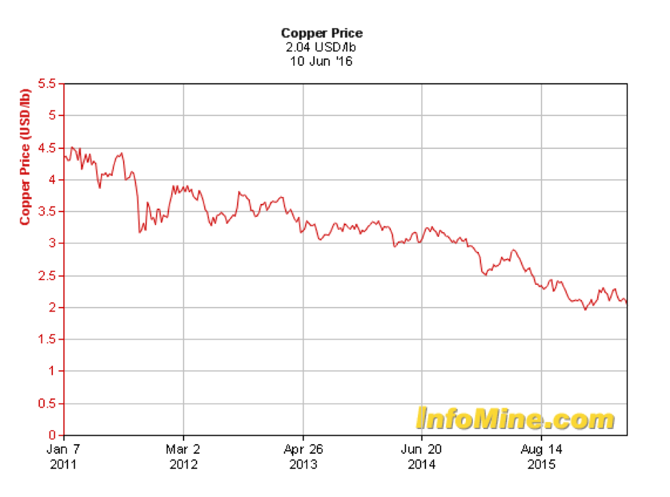
While conventional cable systems use large amounts of copper, commodity prices have been steadily falling for the last several years. Still, copper prices are vulnerable to exploitation and their boom and bust cycles, which might cause concern over medium-term commitments to a particular solution.
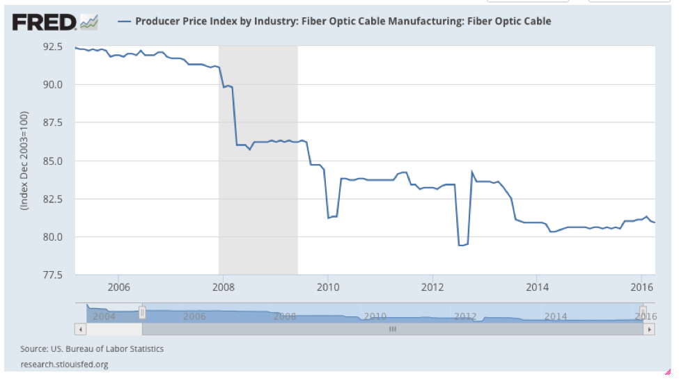
Meanwhile, the cost for fiber cable, components, and hardware has steadily decreased. Copper has an advantage in price over short distances of a few meters, but a fiber solution is less costly for longer runs. This is why Type 3 connections will be favoured for several more years.
Over the long term, fiber optics are definitely the way forward for networking and data transfer. The tools for splicing and connecting cables are getting better and simpler to use, researchers are still exploring the security advantages (optical fibers can be difficult to tap). In the immediate term, it comes down to whether it will help solve a problem. To learn more about what the standards are for optical cables with your favorite interface, take a look at the AIA’s standards here, the EMVA’s standards here, and JIIA here.
More Info about the CLHS:
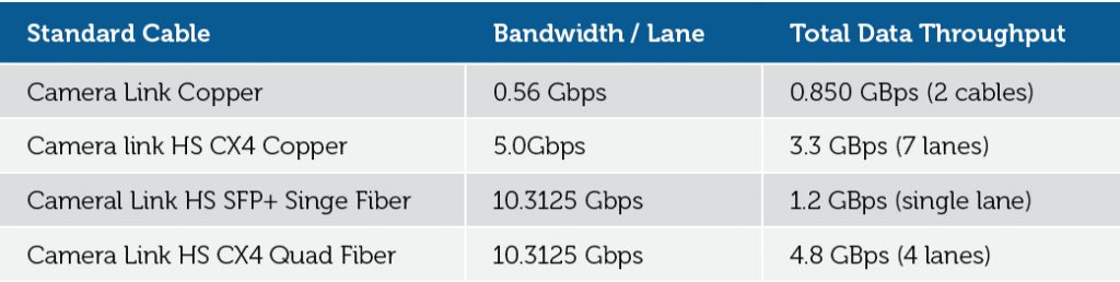
The Camera Link HS (CLHS) standard defines the SFP+ connector for 10 Gbps operation allowing system integrators to choose short reach copper solutions or longer SFP+ transceivers and associated LC fiber cables. In addition, the CLHS standard defines the SFF-8470 connector (CX4) which also supports multiple lanes of data and active optical cables. The CLHS committee has proposed the CX4 connector to the JIIA as an optical connector candidate and is working with optical cable vendors to develop thumbscrew versions. The committee is working to validate this connector solution from the Infiniband proven 5 Gbps to 10 Gbps and beyond. A multilane 10 Gbps connector solution enables decreased camera/frame grabber sizes with higher bandwidths.
 Master of Cables, Part One: Getting Entangled in Machine Vision
  Master of Cables, Part Two: Untangling the Future