

Spinning Disk Confocal Microscopy
Everything we see is thanks to light which passes from objects into our eyes. By using a lens (such as a magnifying glass) we can bend and focus that light, which lets us see smaller objects. Conventional light microscopes are essentially a series of lenses that bend light from a light source, through a sample and into your eyes, or into a camera. This allows us to see ever-smaller objects such as cells and bacteria, which is hugely important for biological study.
Learn more about spinning disk confocal microscopy at Teledyne Photometrics.
However, cells and bacteria (and the smaller structures inside them) are mostly water and are therefore transparent. Imaging tiny see-through bags of water results in images that don’t contain a lot of information, and in microscopy it is vital to have some sort of contrast or dye/stain that will give areas of the sample a colour and make them far easier to see. In addition, what if you only want to image some of the smaller structures inside a cell, like the nucleus or the cell membrane? Colouring the entire cell would make it impossible to localise the areas you are interested in.
Fluorescence microscopy solves both these issues of contrast and localisation. Fluorescence is where an object will emit light after absorbing light. Many different objects exhibit fluorescence, such as minerals (the word fluorescence coming from the mineral fluorite), deep‑sea fish (most famously the jellyfish Aequorea victoria, from which green fluorescent protein (GFP) was discovered), plants, chemicals and many more.
Fluorescent chemicals (known as fluorophores) are used to label samples, and fluorophores are available that emit light in virtually any colour. In a fluorescent microscope, a sample is labelled with a fluorophore, and then a bright light (excitation light) is used to illuminate the sample, which gives off fluorescence (emission light). In this manner, samples are highly contrasted to the black background as the fluorophore emits a bright coloured light. By localising these fluorophores to the area of interest a clear image of any part of a cell can be taken, making fluorescence microscopy a powerful tool for life sciences.
Drawbacks of fluorescent microscopy
In fluorescence microscopes the entire sample is illuminated by the excitation light, and the resulting fluorescence is detected by a camera which records the whole field of view. As the entire sample is flooded with light and all the emitted light is collected, this includes collection all of the out-of-focus light above and below the focal plane, causing blurriness and image degradation. This effect is exacerbated when imaging 3D elements such as cells, which contain fluorophores, areas of auto-fluorescence or liquid-filled areas that scatter light. When imaging such samples vital information can be lost.
Confocal microscopy
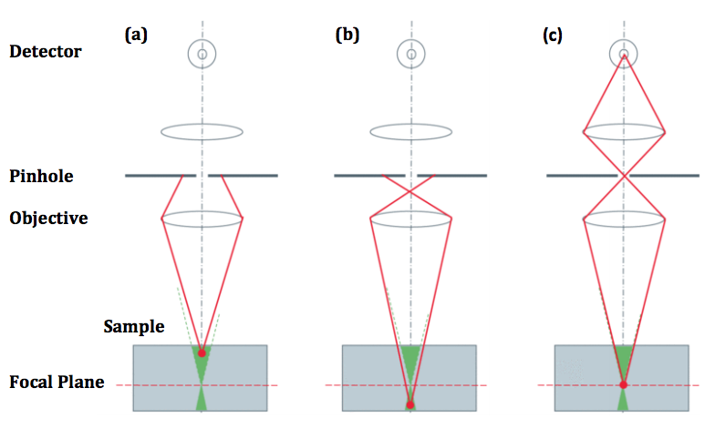
Confocal microscopy improves on standard fluorescence microscopy, as a confocal microscope works by rejecting out-of-focus light from above or below the focal plane using a pinhole, which results in greater resolution, greater contrast and reduced noise. However, this pinhole only images a tiny area of a sample (approx. 100 nm) and consequently needs to be scanned across the whole specimen, which takes time and causes considerable photobleaching.
Rather than a single pinhole, a spinning disk confocal microscope (SDCM) has hundreds of pinholes arranged in spirals on an opaque disk, which rotates at high speeds. When spun, the pinholes scan across the specimen in rows, building up an image. Using a spinning disk vastly improves the speed of image acquisition (allowing for imaging of fast dynamic processes and live specimens), and considerably reduces photodamage and bleaching.
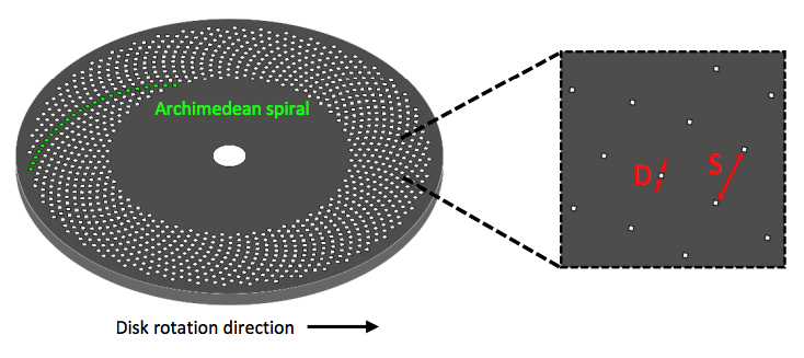
The pinholes in the disk are arranged so that every part of the image is scanned as the disk is turned. By altering the disk rotation speed, pinhole diameter and/or pinhole spacing, the image brightness, contrast and quality can be modified and optimised, making SDCMs highly customisable. However, while larger pinhole diameter results in improved light transmittance through the disk, it also reduces resolution, and while having big pinhole spacing eliminates any pinhole cross-talk, it also reduces light transmittance.
Having small pinholes with large spacing would result in higher axial resolution but the lowest transmittance of light. Light transmittance through the disk can be improved with the addition of a second disk which contains micrometre scale lenses in the place of pinholes. The micro-lens disk focuses light through each pinhole of the primary disk, with considerably improves light transmittance to the sample.
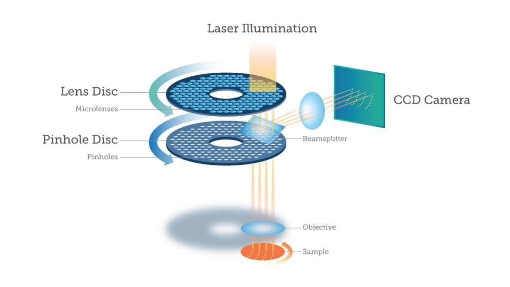
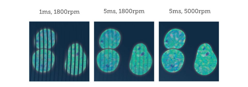
An important point to consider is that SDCMs excite and image multiple points at once, meaning that standard point detectors such as the photo-multiplier tubes (PMTs) used in standard confocal microscopes are insufficient to detect the emitted light. Instead, array‑based detectors are used such as the cutting-edge EMCCD and sCMOS cameras produced by Teledyne Photometrics. These cameras need to have short exposure times due to the speed of the spinning disk, with short exposure times or a slow disk rotation speed resulting in a streaky image. By using cameras that can match high rotation speeds, high-quality images are produced.
In conclusion, spinning disk confocal microscopy offers a clear improvement on standard laser scanning confocal microscopy and conventional fluorescence microscopy, allowing for fast and efficient imaging of live samples, dynamic processes and optical sectioning of 3D samples in 2D slices. Multichannel images can be taken at multiple wavelengths, resulting in high-quality images dense with information, and deconvolution methods exist to further improve contrast and image quality. The main disadvantage of SDCM is that only a small proportion of light is transmitted through the disk to the sample, but with customisable pinhole disks, secondary microlens disks and highly sensitive cameras these limitations can be easily overcome, while also improving imaging speed and field of view even further to produce high resolution images faster than ever.
Learn more about spinning disk confocal microscopy at Teledyne Photometrics.
 Conclusion: Mapping the Efficiencies of 3D Digital Pathology
  Dynamic X-ray Imaging: A Second Look, a New Diagnosis