

The Rapid Deployment of 3D Imaging Applications
3D machine vision is driving exciting new possibilities for faster, cheaper, and more accurate inspection
3D machine vision, or the precise three-dimensional measurement of complex free formed surfaces, is truly a disruptive technology. As 3D imaging gains ground, how can companies get up and running quickly with 3D applications? This article will examine what it takes to make 3D work in your imaging applications with specific recommendations and use case examples.
For many applications, multiple 3D sensors are required. Software for multiple 3D sensors need to support specific functions. We will review these details, after a brief overview of 3D machine vision technology.
3D machine vision technologies
Compared to more conventional 2D imaging, three-dimensional imaging is hard. Commonly used 3D machine vision technologies include stereo vision, Time-of-Flight (ToF) scanning and 3D triangulation.
With stereo vision, images from two cameras are processed to measure the difference in the images caused by the displacement between the two cameras, enabling the system to accurately judge distances. This takes more processing time than 2D systems, but today’s multi-core processors can easily handle real-time 3D machine vision.
Time-of-Flight (ToF) scanning determines the depth, length, and width of an object by measuring the time it takes light from a laser to travel between the camera and the object. Typical TOF 3D scanning systems can measure the distances from 10,000 to 100,000 points on an object every second.
3D triangulation systems use lasers that shine thousands of dots on an object and a camera that precisely locates each dot. The dots, the camera, and the laser form triangles, allowing the system to use trigonometry to calculate the object’s depth even for non-standard sized objects such as multiple parts for an engine component.
Faster and cheaper processing enables more 3D applications
Human eyes and brains often have a hard time processing the extra information available with 3D imaging – just think of watching a 3D movie. However, computers today can do that quite well.
That hasn’t always been the case. In the 1980s, dimensional imaging was merely a research curiosity, only making its way out of the laboratories and into application demonstration in the 1990s. As computers became more powerful in the 2000s, they were able to handle more sophisticated algorithms and process data more quickly. Finally, there were applications where 3D imaging could produce more reliable and accurate results than 2D.
Initially, 3D laser scanners found their way into the oil industry. Geological features could be measured, and oil refineries and other large industrial plants could keep track of geographical shifts or other threats to pipelines and equipment. The potential of a new discovery or the huge expenses of a failure meant that the companies were willing to put up with high costs and complexity. Later, manufacturing industries—particularly automotive—found ways to use 3D imaging for quality control. The construction industry uses 3D scanners to survey and model buildings and city sites.
As processing became easier, and prices came down, 3D imaging found its way into more markets. The medical field began exploring dental applications. Real estate and construction companies could create three-dimensional models of houses and other structures to build, repair, and even sell.
3D imaging leveraging multiple sensors
In certain 3D applications the use of multiple sensors is required. Here are two examples:
Covering a large field of view (FOV) with high resolution. Scanning large objects requires a 3D sensor with a large FOV. This is possible, but in practice it could result in an insufficient resolution for the application and may therefore reduce the precision of the measurements. In this case, setting up multiple 3D sensors next to each other can solve the problem. One example would be the inspection of car indoor roof foam panels. This involves a very large FOV for a rather small depth.
3D is required for any precision depth measurement. For example, solder inspection can only be achieved with precision via 3D. Another example is the inspection of seals on food packaging.
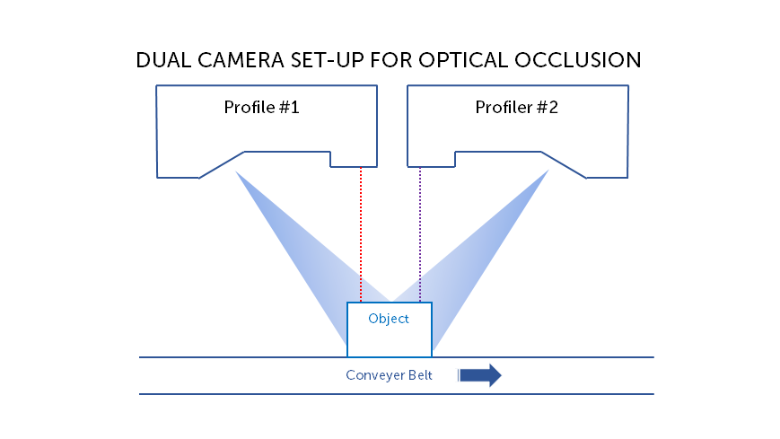
Scanning complex, integral objects is not possible with a single 3D sensor as the laser cannot reach all parts of the object. An integral object is a 3D model of a real object with data points on all surfaces of the object. For example, this could be a machined metal part on which we want to make measurements of various subparts (width, height, angles). Or, these parts may include cavities not seen by single laser. In order to successfully scan these complex parts, we need multiple profilers to be able to reconstruct the total surface. Several configurations of 3D sensors – such as side-by-side, back-to-back, opposite configurations — are possible to allow scanning of all parts and combining them together provides an integral object output.
To do this, we scan a calibration object (e.g., a prism), and compute transformation via a specialized algorithm. We end up with one affine transformation for each profiler to be applied at runtime in order to produce data in a unified coordinate system. It takes all scans and outputs a 3D image of the object:

Software requirements
When multiple 3D sensors are used, the software needs to support the following requirements:
- Timing Synchronization. When multiple sensors are involved, timing synchronization is required to avoid interference between sensors (i.e. prevent one sensor from seeing the laser of its adjacent sensors). To do this, the sensors are configured to strobe lasers and start exposing alternately in time (one after the other). Ideally, this synchronization is organized in such a way that the primary sensor is electrically trigged while sending a software command to all other sensors via Ethernet link. To ensure precise and non-drifting synchronization, the PTP standard (Precision Time Protocol) is used.
- Unified Coordinated System. In a multiple-sensor configuration, each individual sensor has its own coordinate system which needs to be calibrated and transformed into a unified coordinated system for the application. Calibration is performed using a known calibration object on which an algorithm extracts features of interest before computing a transformation (typically rigid transformation based on six degrees of freedom). Once transformations are applied to all sensors and redundant 3D points are eliminated, a unified view of the scanned object is produced and ready for measurements. Calibration object may be of different shapes, sizes and layout. Calibration objects need to be easy to manufacture and easy to mount (often customers produce their own calibration object) while being suitable for extracting features such as corners, lines, vertex, etc.
- Graphical Software. Software provides ability to manipulate the parameters of the system such as timing, layout scenarios, calibration objects, transformations, etc… all in a graphical way in order to ensure an optimal balance between ease-of-use and flexibility.
- Measurements. Measurements are performed on the resulting data in the unified coordinate system. Measurements are defined on primitives such as points, lines and circles. There primitives are fitted to the real data points for maximum precision.
A rapidly growing global market
3D machine vision was developed to enable automated quality control. But it is now being applied much more widely, in concert with automation and machine learning. Quality control has evolved into production optimization—systems that detect potential problems at a very early stage, identifying the causes and automatically fixing them on the fly.
Analysts are predicting double-digit growth across the industry: 3D modelling, scanning, layout and animation, 3D rendering, and image reconstruction. The 3D camera industry is forecast to reach US$17.6 billion in 2025 and the 3D scanning segment is expected to reach US$14.3 billion by 2025. Growing use of 3D imaging in smartphones, cameras, and televisions continues to drive demand, and the use of 3D imaging software in the automation industry continues to propel further adoption as implementation becomes less burdensome, and easier to deploy.
 Has 3D finally come of age?
  Seeing into the future with 3D machine vision