

What is Total Internal Reflection Fluorescence Microscopy?
Known as TIRF, this innovative technique for visualizing structures in living systems takes advantage of reflected light for improved accuracy
Fluorescence microscopy is a fundamental set of techniques in the life sciences for visualizing structures in living systems. Typically, a fluorescent molecule (fluorophore) is associated with a structure of interest in a biological sample. When the sample is illuminated with light of an appropriate wavelength, the fluorophore becomes excited and emits photons of a different wavelength, these emitted photons are detected by a scientific camera and reveal information about the structure of interest that the fluorophore is associated with.
The resolution at which fluorophores can be visualized depends greatly on the preparation of the sample, the sensitivity of the camera, the intensity of the excitatory light, the objectives used in the microscope, and many more factors. However, image quality and resolution in general are limited by out of focus light being collected. In standard fluorescence microscopy (widefield) the sample is bathed in light, this means while signal is collected from the plane of interest (the focal plane where the microscope optics are focused), signal is also collected from above and below this plane. This is known as out-of-focus light and can lead to blurry, low-quality images.
While techniques such as spinning disk confocal microscopy or light-sheet microscopy can eliminate this out-of-focus light with the use of pinholes or a sheet of light respectively, there are other methods that take advantage of the reflection of light. One of these examples is total internal reflection fluorescence (TIRF) microscopy.
Total Internal Reflection
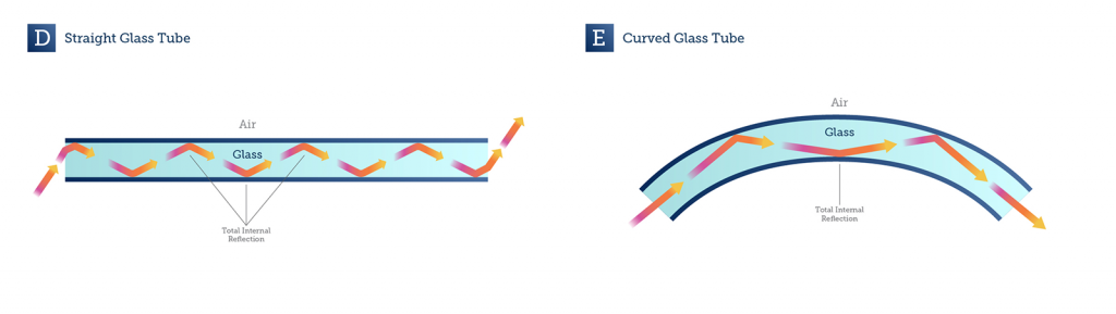
Light can be reflected by a range of mediums, such as glass, air or water. When light moves at a certain angle across the boundary from one medium to a second medium that has a different refractive index, the light can be completely reflected back into the first medium. This phenomenon is known as total internal reflection. At other angles the light would be refracted into the second medium, but at certain angles total internal reflection occurs, as seen in Fig.1.
In the mid-1950s, E.J. Ambrose had the idea to use total internal reflection in microscopy, in order to image cells that were adhered to a glass surface (Ambrose 1956), an idea that was expanded into total internal reflection fluorescence (TIRF) microscopy by Daniel Axelrod in 1981 (Axelrod, 1981).

TIRF Microscopy
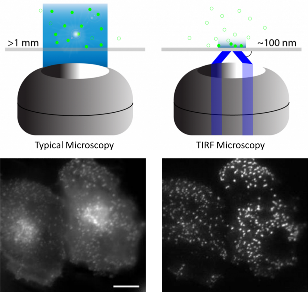
In standard fluorescence microscopy, the excitation light is focused through an objective to the sample, where it illuminates the focal planes and out-of-focus planes. In TIRF microscopy, the excitation light comes in at an oblique angle (due to microscopy objectives or prisms) and experiences total internal reflection off the surface of the sample, or the surface the sample is adhered to.
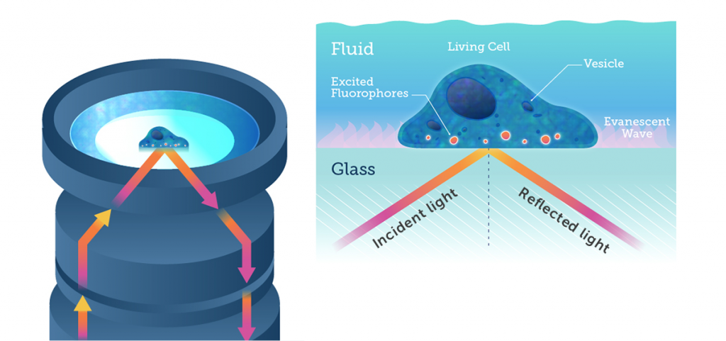
When total internal reflection occurs, an evanescent field or wave is produced at the site of reflection, namely at the boundary between two mediums. This evanescent wave decays exponentially as it travels from the site of reflection, typically travelling only 50-100 nm. This effectively means that only the fluorophores within the 50-100 nm section of the sample closest to the reflection site are excited, and only this area is imaged. By only imaging such a select and specific area of the sample, there is no out-of-focus light and image quality is greatly improved. In TIRF microscopy, axial resolution is greatly improved, the total light dose to the cell is minimized (reducing bleaching and phototoxic effects), and the removal of out-of-focus fluorescence results in a much higher signal-to-noise ratio.
Due to these advantages, TIRF microscopy is a highly sensitive image technique and is a powerful option when detecting fluorophores close to an interface, most often used with live cells in order to image the cell surface and study the cell membrane.
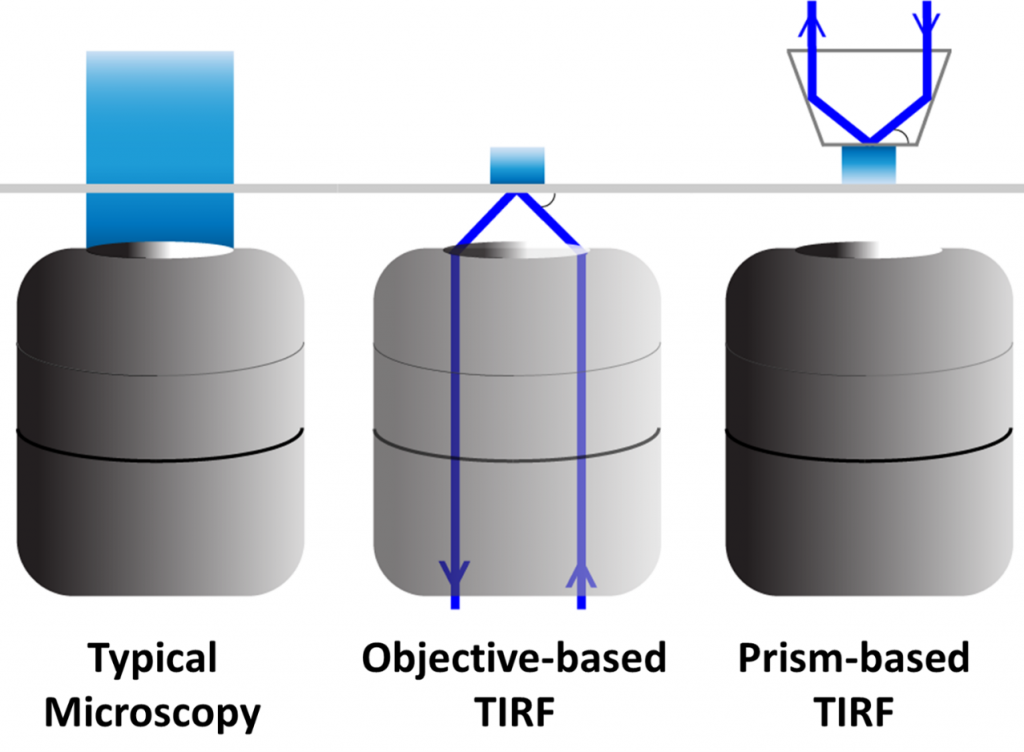
The optics and light path in TIRF microscopy can be generated in one of two main ways, either using a microscope objective lens or using a lens-free approach with a prism.
With objective-based TIRF, a high refractive index of glass (measured in objectives by the numerical aperture) is needed in order to get a large enough angle to produce total internal reflection. Some specific TIRF lenses have been developed, allowing for control over the size of the evanescent wave.
For prism-based TIRF, the microscope objective isn’t needed for illumination, and is just used to detect the excitation light. The prism is placed on the opposite side of the sample and is easily adjustable, but can only be done on thin, transparent samples due to needing the wave to travel through to the detection objective. Prism- and objective-based TIRF can be seen in Fig.3.
TIRF Microscopy Applications
Live cell imaging can benefit greatly from the very thin optical section of TIRF microscopy, as it allows for investigation at or near the cell membrane. However, any imaging further than 100 nm into the sample is typically not possible, meaning TIRF is naturally mostly used for surface interface studies.
For this reason, ligand-receptor binding, protein-membrane trafficking, synaptic vesicle fusion, and cell adhesion proteins have been extensively studied with TIRF microscopy in cells as well as other events near the membrane such as actin dynamics in filopodia and G-protein coupled receptor transduction events. The reduction in light intensity and low photo-toxicity allows for multiple exposures without affecting the health of the sample which is ideal for long time-lapse studies or fast, high temporal resolution imaging.
There has also been success with combining TIRF with other techniques, greatly increasing the versatility and power of the technique.
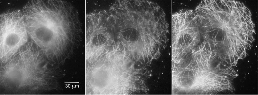
In 2006, TIRF was successfully combined with structured illumination microscopy (SIM) to improve the lateral resolution of TIRF to super-resolution distances of ~90 nm. The addition of SIM, which uses phase and frequency information, also provides depth information and enabling high resolution 3D imaging, as well as multicolor TIRF imaging. TIRF has also successfully been combined with other super-resolution imaging techniques such as PALM and STORM.
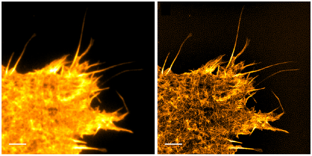
Further improvements of TIRF have come from manipulating TIRF itself, rather than through additional processing. Spinning-spot TIRF is an improvement over objective-based TIRF where the laser coming in at the back focal plane of the lens is rotated around in a donut shape. Instead of the illumination coming from a single angle, the beam is rotated faster than the exposure time of a frame, effectively averaging the illumination from all radial positions giving a uniform spot. The spinning illumination then averages out the inconsistencies in the field, producing clearer, higher signal-to-noise images than traditional TIRF, as seen below. Spinning-spot TIRF, like regular TIRF, can also be used in combination with other methods described above.
Cameras For TIRF
The applications of TIRF microscopy are varied and include both low- and high-light applications. However, typically high spatial resolution and/or fast live imaging are motivators for using TIRF microscopy.
The technical necessity of using a high numerical aperture lens to achieve TIRF, coupled with the emphasis on high spatial resolution, means that TIRF users require a camera with appropriately sized pixels for Nyquist sampling at diffraction limited resolution whilst being sensitive enough for low-light single molecule fluorescence applications.
Sensitivity is often the first concern for TIRF imaging, with back-illuminated, 95% quantum efficient sCMOS sensors being the first choice. To achieve diffraction limited resolution, the next concern is matching the pixel size to the magnification being used. A pixel size around 10-11 μm is optimized for a 100x lens and a pixel size around 6-7 μm is optimized for a 60x lens, both common pixel sizes of sCMOS cameras.
A large sensor area can also be important for some TIRF applications. sCMOS sensors are generally larger than EMCCD, where the most common EMCCDs have an 11 mm diagonal field of view and sCMOS sensors tend to range from 18 mm to 32 mm to better take advantage of modern, large field of view microscopes.
For high temporal resolution applications such as imaging protein dynamics or receptor trafficking, faster frame rates can be achieved with sCMOS cameras with less region cropping than EMCCDs to combine high speeds with large fields of view.
Summary
TIRF microscopy relies on the evanescent field generated by total internal reflection, to excite a very thin <100 nm optical section at the interface between the surface and the sample. It has become a stand-out technique in live cell and single molecule imaging due to its exceptional axial resolution and low total luminance. In combination with other methods, such as FRET and super-resolution techniques, it is widely used to answer questions in the life sciences.
Learn More: Application Note on TIRF Microscopy
References
Axelrod D. (1981). Cell-substrate contacts illuminated by total internal reflection fluorescence. The Journal of Cell Biology, 89(1), 141–145. https://doi.org/10.1083/jcb.89.1.141
E.J. Ambrose (1956). A Surface Contact Microscope for the study of Cell Movements, Nature, 178, 1194 (1956), https://doi.org/10.1038/1781194a0
Ellefsen, K. L., Dynes, J. L., & Parker, I. (2015). Spinning-Spot Shadowless TIRF Microscopy. PLoS ONE, 10(8), e0136055. http://doi.org/10.1371/journal.pone.0136055
Mattheyses, A. L., Simon, S. M. & Rappoport, J. Z. (2010) Imaging with total internal reflection fluorescence microscopy for the cell biologist. J Cell Sci. Nov 1; 123(21): 3621–3628. doi: 10.1242/jcs.056218
Young, L. J., Ströhl, F., & Kaminski, C. F. (2016). A Guide to Structured Illumination TIRF Microscopy at High Speed with Multiple Colors. Journal of Visualized Experiments : JoVE, (111), 53988. Advance online publication. http://doi.org/10.3791/53988
 What Is Light Sheet Microscopy?
  What is Voltage Imaging?