

What is Voltage Imaging?
Modern voltage imaging can show us cell signals with subcellular spatial resolution and fast temporal resolution, helping us understand functionality in living organisms.
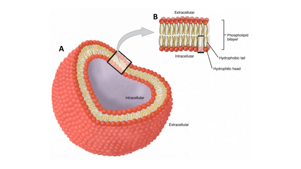
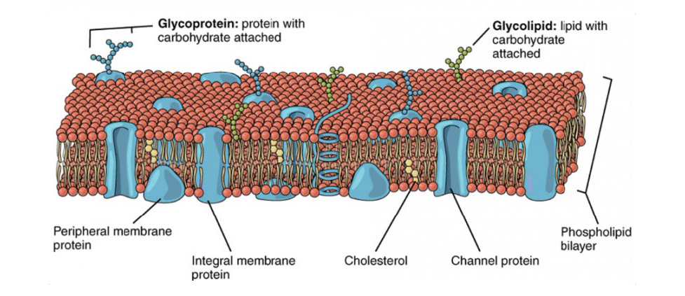
All animal cells are surrounded by a cell membrane, composed of a double layer of lipids with proteins embedded in it, as seen in Fig.1. Standard electricity (such as in your home) mainly involves the movement of electrons; but electrophysiology involves the movement of ions (atoms that have a charge). In the body, some of the most common ions are sodium (Na+), potassium (K+), calcium (Ca2+) and chlorine (Cl–). The area inside cells (cytosol) and outside cells are filled with millions of ions, and the cell membrane acts to control the movement of ions in and out of the cell.
This movement of ions across the membrane can be measured, and results in voltage changes. These changes are marked by voltage indicators, and the imaging of these dyes is known as voltage imaging.
Voltage Indicators
The constant presence of ion concentration gradients across the membrane leads to a difference in voltage between the interior and exterior of a cell. This is called the membrane potential, and is typically between 40 mV and -80 mV. For most cells, the membrane potential is stable at these typical values, which is also termed the resting potential.
Voltage indicators are substances that change in response to changes in voltage. By treating cultures of brain or heart cells with these indicators, their voltage activity can be observed and measured. A large number of processes in the body are accompanied by changes in the membrane potential, such as neurons in the brain signalling each other, and myocytes of the heart regulating the heartbeat.
Imaging with these indicators is known as voltage imaging, which allows for direct fluorescence imaging of voltage changes, an attractive method for studying neuronal circuits and heart muscle, and a useful complement to traditional electrode-based methods or calcium imaging.
However, there are several challenges involved with voltage imaging, including:
- Neuronal signaling is very fast (~1 ms) and any voltage indicator needs to respond even faster than this (sub-milliseconds) in order to best resolve an image.
- While calcium imaging can utilize any flux in calcium ions throughout a cell, voltage imaging has to be localized to the cell membrane in order to function.
This means that design of voltage indicators is a greater challenge as they won’t function unless they can localize to the membrane, and only a limited number of dye molecules will receive a useful signal as the membrane has a low volume compared to the interior and exterior of a cell. The combination of these two factors (fast biological events and small workable volumes) means voltage indicators need to be bright, stable, highly sensitive and not disrupt normal cell activity. Despite these demands, voltage imaging has been part of electrophysiology for nearly 40 years and a number of viable indicator families have been developed in this time.
Voltage-Sensitive Dyes
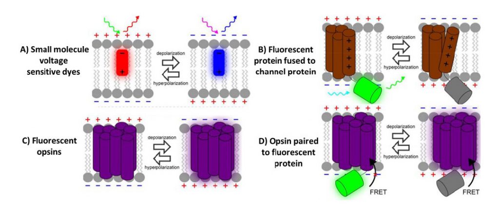
The earliest indicators were small fluorescent dye molecules, discovered after Larry Cohen and colleagues screened thousands of dyes to search for voltage-sensitive dyes (VSDs). The first was merocyanine 540, which displayed voltage-sensitive fluorescence and was used to track signalling in a giant squid, and a number of other VSDs have been discovered since. These VSDs bind to the membranes of cells and change their fluorescence when the cell membrane potential changes.
VSDs can be broadly split into two categories, slow dyes and fast dyes. Slow dyes respond to membrane potential changes in milliseconds to seconds and are therefore best suited to measure the resting potential of large groups of cells, as they cannot measure fast neuronal communication. Fast dyes respond in microseconds and in proportion to the change in membrane potential, making them much faster and quantifiable, but often feature low sensitivity.
Both slow and fast dyes had their own applications, but further developments in VSDs resulted in more modern techniques, such as photoinduced electron transfer (PET). This technique involves the transfer of electrons from a molecular wire to an indicator, this process is sensitive to external electric fields (and therefore the membrane potential) while also being very fast, featuring enough speed to capture neuronal communication.
Despite these advances, VSDs can be limited due to their inability to target specific neuronal populations, as well as signal interference from inactive cells or undesired active cells. In addition, VSDs respond unreliably and often require numerous repeats and optimization steps, and the dye can cause permanent changes in cells that are treated with VSDs, even changing the photodynamics.
A better indicator would have the ability to specifically target sub-populations of cells or even proteins within cells, such as membrane channel proteins or other membrane potential-related units. This advance comes in the form of fluorescent proteins.
Genetically Encoded Voltage Indicators
Fluorescent proteins (FPs) such as green fluorescent protein (GFP) have revolutionized the field of biological imaging, allowing organic proteins that occur in nature to fluorescently label any protein, cell component or complex in a non-invasive, fast and sensitive manner. In terms of voltage imaging, Iscaoff and Siegel fused GFP to a membrane potassium channel in 1997, making the first voltage sensitive fluorescent protein, called FlaSh. These indicators are typically termed genetically encoded voltage indicators (GEVIs).
In fact, fusing a FP to any protein that undergoes a conformational shape change in response to changes in calcium ion concentrations or membrane potential creates a viable indicator. These FP-based indicators are encoded in DNA and can be expressed by any cell after some genetic engineering, meaning that voltage imaging can be performed in large live animals or tissue slices. Researchers fused GFP to a wide variety of voltage-related cell components, resulting in three generations of GEVIs.
The first generation consisted of the original FlaSh and other GEVIs where GFP was fused to a potassium or sodium channel, such as VSFP1 (2001) and SPARC (2002). This first generation has poor targeting to the cell membrane and low expression, but established the fundamentals for GEVIs.
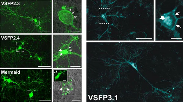
The second generation was based on the discovery of a protein (Ci-VSP) which had a single voltage sensing domain, unlike the previous sodium/potassium channels that had four, and it could function by itself in isolation. This allowed for much simpler GEVIs which better targeted the plasma membrane, such as VSFP2 (2007-2009), which could also use multiple different colours of FP (yellow, red, cyan) so that multiple indicators could be used simultaneously. The drawback was that these GEVIs had a slow response to changes in membrane potential.
The third generation was similar to the second but involved a much stronger coupling between the voltage-sensing domain and the FP with a shorter linker section, and only involved the use of one FP rather than multiple. This made them much faster and able to resolve quick neuronal signalling, but limited to only one colour.
Opsins
Rather than fusing FPs with voltage-related proteins, another option involves the naturally light sensitive channel proteins in the opsin family of proteins (like rhodopsin, a protein that allows our eyes to detect light). One bacterial opsin (creatively named bacteriorhodopsin) has been used widely in optogenetics, where light is used to induce a conformational change in the channel protein, turning cells ON and OFF with light. In 2011, Larry Cohen and colleagues found a way to reverse this process, where a change in membrane potential changed the channel conformation, which then changed the fluorescence of the opsin.
These opsin-based GEVIs have high sensitivities to changes in voltage and active quickly, but also require a fairly intense light to achieve fluorescence, meaning there is a chance for the cells to develop photodamage. However, opsin GEVIs have prevent be a robust platform for study, with several iterations of different GEVIs created from small tweaks to the genetic code, resulting in improved brightness and reduce initial light excitation.
In addition, opsin-based GEVIs have been further combined with additional FPs to make Opsin-FP FRET pair GEVIs, where FRET is Förster resonance energy transfer (FRET), namely how two fluorescent molecules can exchange energy when they are close enough together (within ~10 nm). This allows for great flexibility when choosing the voltage sensor and optical reporter, as changes in membrane potential alters the spectrum of the opsin and cause a convenient signal for monitoring voltage.
Cameras For Voltage Imaging
Voltage imaging is an application featuring very high speeds, meaning that a high-speed sCMOS camera is most suited for voltage imaging in order to best capture and quantify the rapidly-changing signals. As this imaging can occur across large tissues or between single cells, it is best to match the pixel size of the camera to the magnification and field of view in the experiment, in order to resolve at Nyquist and obtain the best images.
Summary
Voltage imaging is a powerful and flexible technique. The constant advancements in voltage imaging from small molecule VSDs to FRET-pair GEVIs have led to voltage imaging becoming a viable alternative to more invasive voltage-recording methods like electrode-based recordings. Modern voltage imaging can display cell signals with subcellular spatial resolution and fast temporal resolution, enough to match neuronal cell signalling. In terms of speed, voltage image is much faster than calcium imaging and has been used in many experiments on live cells and large model organisms.
Overall, voltage imaging is an important part of electrophysiology that constantly improves over time, and is likely to continue to play a big role far into the future as camera speeds continue to improve.
 What Is Light Sheet Microscopy?
  An Introduction to Multitrack Spectroscopy and its Applications