Has 3D finally come of age?
So nice, we did it thrice: Adding an extra dimension to imaging
If you looked only at the movie industry, you could be forgiven for thinking that 3D was a failure. Repeatedly, 3D has been promoted as the next big thing in movies, only for it to fade within months of its last showing. In the perhaps less glamourous world of machine vision, where 3D imaging remains several years behind 2D in terms of image quality, rendering, and ease of use (despite the hype and financial successes to date) it is seeing a resurgence for a growing number of applications. In this post, we will provide some background for four popular techniques for 3D imaging.
Slow starts for intensive imaging
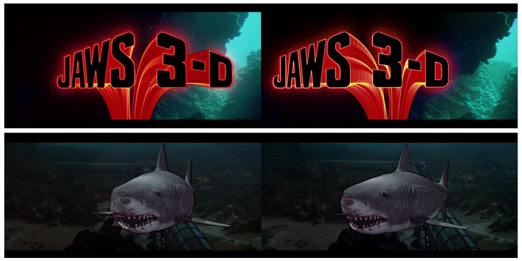
First, compared to more conventional 2D imaging, three-dimensional imaging is hard. Just watching a 3D movie can trigger all kinds of disorders as our brains fight to process what we’re seeing. Eyes and brains observing 3D need more time to understand what they’re seeing than they need for 2-D shots. Stereoscopic 3D, which involves two cameras filming the same scene simultaneously (more on this later), is the oldest and most common form, and is based on how we see in three dimensions. How close or far apart the cameras are can have dramatic effects on the type and quality of the resulting 3D image. Second, quickly moving objects, spinning backgrounds, and other kinds of motions can render 3D movies unwatchable. Complexities with projection were also a problem throughout 3D movie history. Projectors needed to be more precisely calibrated and even today, poor technique to compensate for the polarized light filter that allowed the two images to be projected simultaneously in theaters led to 3D movies getting a reputation for being ‘too dark’ or muddy.
How to make 3d image work: Take out the humans
Almost all of these problems of perception and projection go away when it comes to industrial imaging. While humans have a hard time processing this extra information, computers today can do quite well. It hasn’t always been that way. The dramatic increase in the amount of information involved with 3D imaging makes it harder to capture and handle.
It took a while for computing power to catch up: dimensional imaging was merely a research curiosity in the 1980s, only making its way out of the laboratories and into application demonstration in the 1990s. As computers became more powerful in the 2000s, able to handle more sophisticated algorithms and process data more quickly, there were finally applications where 3D imaging could produce more reliable and accurate results than 2D.

Initially, 3D laser scanners found their way into the oil industry. Geological features could be measured, and oil refineries and other large industrial plants could keep track of geographical shifts or other threats to pipelines and equipment. The potential of a new discovery or the huge expenses of a failure meant that the companies were willing to put up with high costs and complexity. Later, manufacturing, particularly the auto industry, found ways to use 3D imaging for quality control. The construction industry still uses 3D scanners to survey and model buildings and city sites.
As processing became easier, and prices came down, 3D imaging found its way into more markets. The medical field began exploring dental applications. Real estate and construction companies could create three-dimensional models of houses and other structures to build, repair, and even sell. And, in a full loop, the entertainment industry was able to use 3D scans to put realistic objects in filmed 2D movies as well as environments and even people. This is extending to video games, virtual reality, and augmented reality.
Building momentum
Increasing automation and monitoring, the use of robotics, and other aspects of Industry 4.0– initiatives are further increasing demand for 3D imaging solutions. The traditional 2D vision approach no longer offers the level of accuracy and distance measurement essential in complex object recognition and dimensioning applications, and it cannot handle complex interaction situations such as the growing trend for human/robot co-working. Growing use of 3D imaging in smartphones, cameras, and televisions continues to drive demand, and the use of 3D imaging software in the automation industry continues to propel further adoption as implementation becomes less burdensome, and easier to deploy.
The high cost of 3D imaging software and solutions may still be impeding growth, but analysts are predicting double-digit growth across the industry: 3D modelling, scanning, layout and animation, 3D rendering, and image reconstruction. The 3D camera industry is forecast to reach US$17.6 billion in 2025 and the 3D scanning segment is expected to reach US$14.3 billion by 2025.
Key techniques of 3D imaging
To better understand how 3D imaging works for industrial markets, it helps to look at the common techniques employed. Today there are four main techniques: Stereo vision, structured light 3D imaging, laser triangulation and ToF. The last three are part of the ‘active’ imaging family that require the use of an artificial source of light.
1. Stereo vision
This method, used in many of the afore-mentioned 3D movies, requires two cameras that are mounted to obtain different visual perspectives of an object. Calibration techniques are used to align pixel information between the cameras and extract information about depth – similar to how our brains work to visually measure distance. Therefore the transposition of the cognitive process into a system requires a significant computational effort.
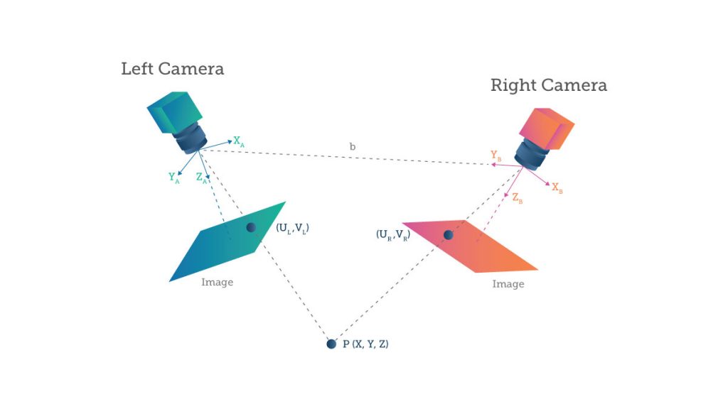
This keeps costs down as standard image sensors can be used. The more sophisticated the sensor (for example, a high-performance sensor or global shutter), the higher the cost of the system. The distance range is limited by mechanical constraints: the requirement for a physical baseline results in the need for larger dimension modules. Precise mechanical alignment and recalibration are also needed. In addition, this technique does not work well in poor or changing light conditions and is very dependent on the object’s reflective characteristics.
2. Structured light
In structured light, a pre-determined light pattern is projected onto an object, and depth information is obtained by analysing how the pattern is distorted. There is no conceptual limit on frame times, no motion blur and it is robust against multi-path interfaces. However, the active illumination requires a complex camera, and precise and stable mechanical alignment between the lens and pattern projector is also required. There is a risk of de-calibration and the reflected pattern is sensitive to optical interference in the environment as well as being limited to indoor applications.
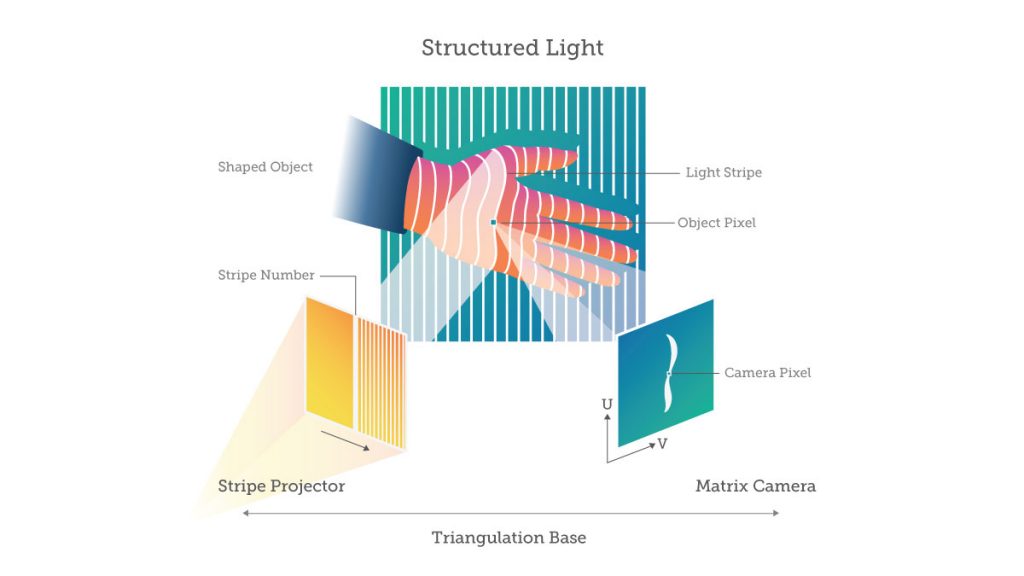
Principles of a projected structured-light 3D image capture method. (a) An illumination pattern is projected onto the scene and the reflected image is captured by a camera. The depth of a point is determined from the relative displacement of it in the pattern and the image. (b) An illustrative example of a projected stripe pattern. In practical applications, typically IR light is used with more complex patterns. (c) The captured image of the stripe pattern reflected from the 3D object. (Source)
This low-cost 3D scanner is based on structured light which adopts a versatile colored stripe pattern approach. The scanner has been designed according to the next requirements: Medium-high accuracy, ease of use, affordable cost, self-registered acquisition, and operational safety.
This kind of approach lets you build accurate models of real 3D objects in a very cost- and time-effective manner. You could build something like this at home with for a few hundred dollars using a video projector, webcams, and some open source software!
3. Laser triangulation
Laser triangulation systems measure the geometrical offset of a line of light whose value is related to the height of the object. It is a one-dimensional imaging technique based on the scanning of the object. Depending on how far away the laser strikes the surface, the laser dot appears at different places in the camera’s field of view. This technique is known as triangulation because the laser dot, the camera and the laser emitter form a triangle. A classical high speed global shutter sensor can be used but a dedicated sensor will achieve much better performance of accuracy and speed.
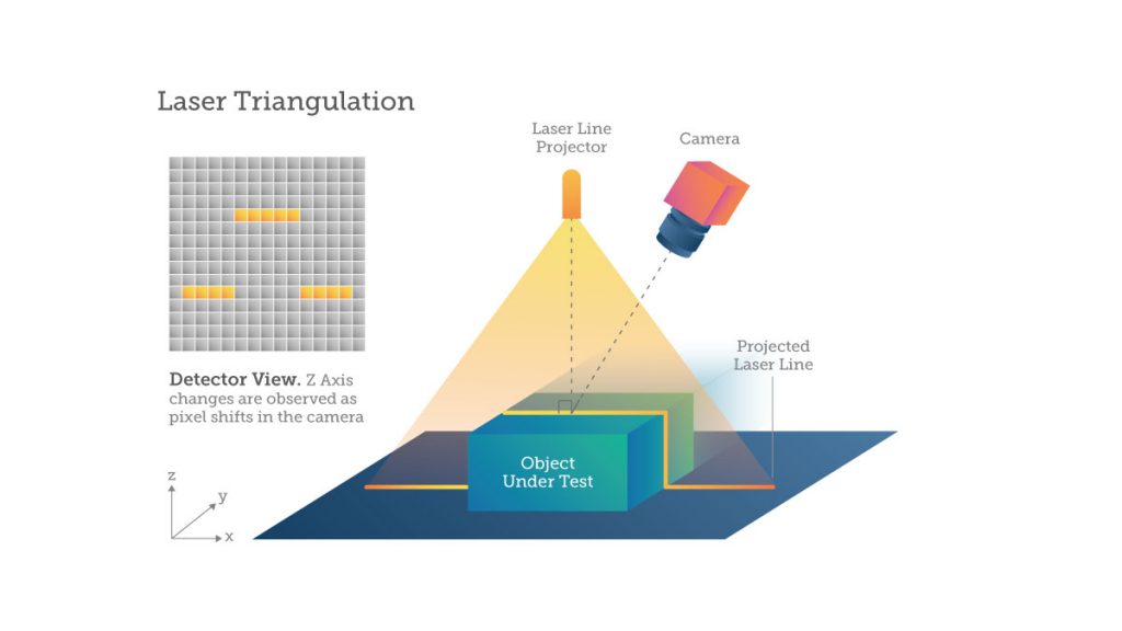
High-resolution lasers are typically used in displacement and position monitoring applications where high accuracy, stability and low temperature drift are required. The downside is that this technique only covers a short range, is sensitive to ambient light and is limited to scanning applications. Complex algorithms and calibration are also required. In addition, this technique is sensitive to structured or complex surfaces.
The main advantage of laser triangulation is its low price, with the first DIY models available for only a few hundred euros. Its acquisition speed (less than 10 minutes on average for an object) and its precision level (of the order of 0.01 mm) also make it a popular technology.
As for the disadvantages, it should be noted that the digitization of transparent or reflective surfaces can prove difficult, a problem that can be circumvented by using a white powder. Its limited range (only a few meters) also reduces the number of possible applications.
4. Time of Flight
This technique represents all the methods which implement a measurement of the distance from a direct acquisition or a calculation of the double time of flight of the photons, between the camera and the scene. This measurement is performed either directly (D-ToF) or indirectly (I-ToF). The D-ToF concept is straightforward but requires complex and constraining time-resolved apparatus whereas the I-ToF can be operated in a simpler way: a light source is synchronised with an image sensor. The pulse of light is emitted in phases with the shuttering of the camera. The light pulse desynchronization is used to calculate the ToF of the photons and this enables the distance between the point of emission and the object to be deduced.
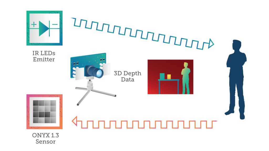
This ensures a direct measurement of depth and amplitude in every pixel. The image is called the depth map. The system has a small aspect ratio, a monocular approach with easy once-in-a-lifetime calibration and operates well in ambient light conditions. Drawbacks include the need for active illumination synchronisation and the potential for multi-path interference and distance aliasing.
The techniques compared
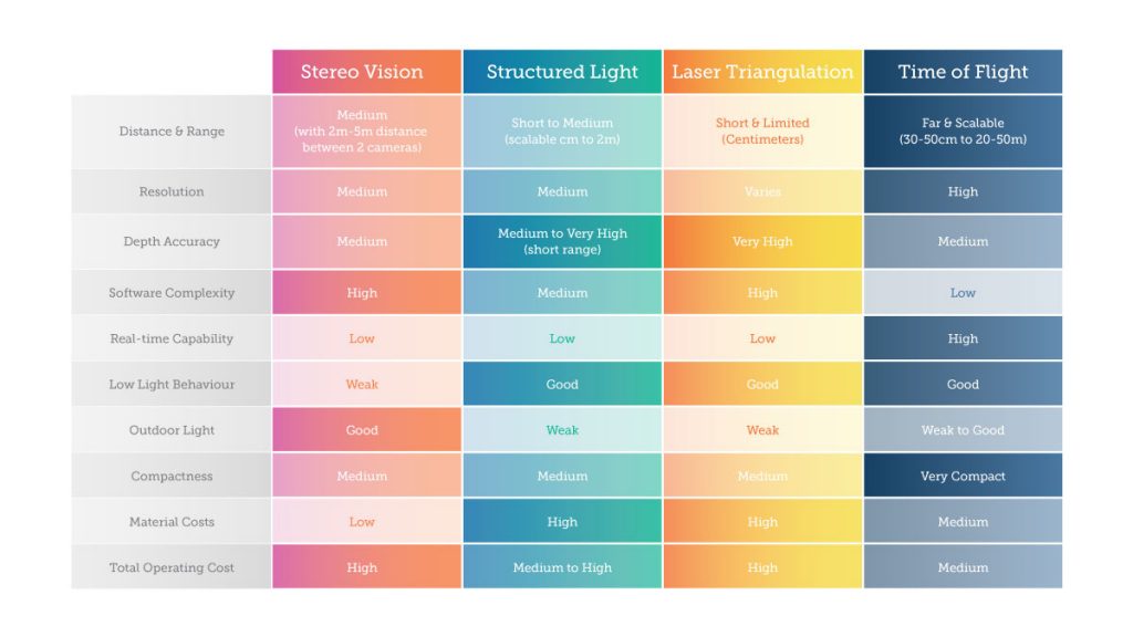
Currently, there are only a few 3D systems in use, mainly based on 3D stereo vision, structured light cameras or laser triangulation. These systems operate at fixed working distances and require significant calibration efforts for specific areas of detection.
The ToF systems overcome these challenges giving more flexibility from an application point of view. Today, due to pixel complexity or power consumption, most commercial solutions are still limited in image resolution to VGA (Video Graphics Array) or less.
Looking forward
Time-of-flight has many advantages that make it the frontier for new applications and technologies. Today mobile phones are using structured IR light for enhanced photography and AR applications. But now analysts are predicting that the next generation of phones will add time-of-flight imaging to enable new augmented reality use cases. Imagine being able to 3D-map any room you’re in from your phone!
The idea of Industry 4.0 is that all these technologies will continue to converge. Once again, the oil and gas industry continues to push industrial applications by integrating 3D sensors with the internet-of-things and augmented reality.
As 3D imaging becomes more accurate, easier to use, and more cost-effective to employ, it’s clear that the next frontier for machine vision and intelligence will be devices and machines that can use 3D imaging information to sense and understand the world, navigate in the environment, and interact with humans in natural ways. Many of these technologies still need to be developed, but we can see what real-time 3D-sensing technologies and their deployment in a new class of interactive and autonomous systems will ‘look’ like.


 3D Imaging is coming to the Tokyo 2020 Olympics
  Seeing into the future with 3D machine vision